5G HO Setup: Handover Testing in Cabled Setup
Handover Test Setup
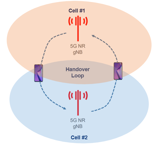
Handover, or handoff in 5G NR or 4G LTE happens when a Data/Voice call is transferred from one cell to the an adjacent cell as the Mobile user moves through the network coverage area. Before any base station software is released for field, it goes through multiple level of testing’s (regression, load etc.) in Vendor’s and Customer’s Lab. This kind of testing in Lab is mostly done in cabled environment to avoid interference for self and to other cells.
In this post we will discuss about cabled handover setups considering following topology for 5G RAN.
- Inter CU handover
- Intra CU and Inter DU handover
- Intra DU handover
Objective & Principle
The objective of handover cabled setup is to simulate the field over the air scenario mean during handover signal from serving cell worsen and neighbors cell signal becomes better. Considering this in cabled setup, we need to mix the signal from two cells and control the signal path from both cell in a such way that one cell signal reduce and other cell signal increase and vice versa.
Features of Test Setup
- Setup is applicable for 4G and 5G
- Valid for Inter/Intra Frequency
- Automation is possible
- Sanity, Regression, Load testing possible (Load testing with Multi UE simulator instead of Real UE)
Setup Hardware Requirement
- Two Radio as Source and Target Cell
- Programable Attenuator: To control signal path
- Power Splitter/Combiner: To mix the both cell
- RF Cables: Connectivity
- Test UEs with Logging Capability
Test Setup Connection Diagrams
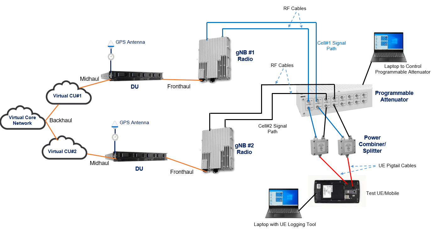
Inter CU handover

Intra CU and Inter DU handover
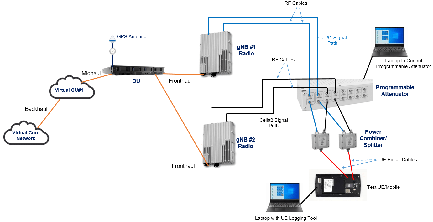
Intra DU handover
Test Setup Verification and Handover Execution
The verify first verification before attempting for HO test, one should try to test that Mobile should be able to attach individual cells. This can be verified setting max attenuation in cell#1 signal path (Port 1,2) mobile should attach to cell#2 and When setting max attenuation in cell#2 signal path (Port 3,4) mobile should be able to attach to cell#1.
While performing handover, you have to create a sequence script where we can control the signal path from two cells. Some digital attenuator allows this to control or create handover sequencer using GUI as shown in below figure. When creating script or configuring HO sequencer we need to to be careful on the attenuation step and interval (dB/sec), if the interval is low or step is high can cause for radio link failures (RLFs).
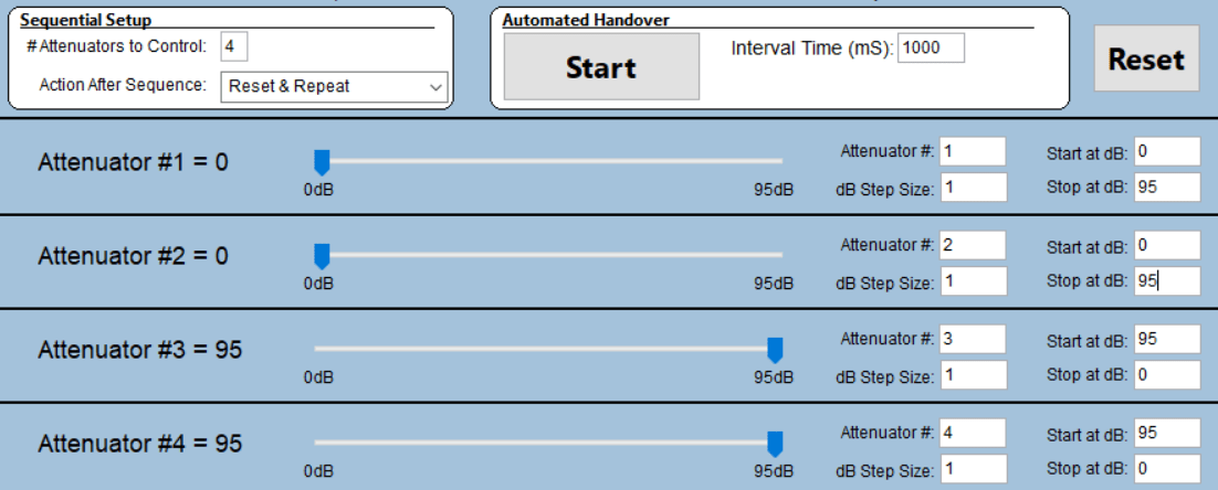
As shown in above figure, the initial attenuation configured on Port#1 & Port#2 is zero, then mobile will attach to cell#1, the HO sequencer increase 1 dB/1 sec attenuation and decrease 1dB/ 1 sec on Port#3 & Port#4. At some point, cell #2 signal will become better than cell# 1 result in Handover and repeat vice versa.
Related Post
- Linux Basic Commands
- 4G LTE Important QXDM Log Packets
- Iperf : A Tool for Network Testing
- tcpdump for Linux System: A Tool for IP Packet Analysis