5G NR-PDCCH Channel Overview and Processing
5G PDCCH Channel Overview
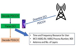
The physical downlink control channel (PDCCH) in NR carries Downlink Control Information (DCI). In this post we will understand how PDCCH operates by describing its physical layer structure, and the carried information. PDCCH channel is referred to as the heart of NR air interface.
PDCCH Channel Characteristics
- NR’s PDCCH is similar to LTE , but because NR has a wider bandwidth and different SCS spacing, so NR’s PDCCH is a bit complex
- PDCCH carrying the data is the DCI – Downlink Control the Information.
- A DCI includes PDSCH and PUSCH transmission resource scheduling information, in addition to uplink power control (PUSCH, PUCCH, SRS) indication , slot format indication, which PRB and OFDM symbols of the UE do not map data, and so on.
- The PDCCH dynamically sends control information to the UE , and the UE needs to read the control information to know when ( time domain), where (frequency domain) and how to demodulate/decode PDSCH (downlink), and when (time domain) Where ( frequency domain) and how to assemble and send PUSCH data (uplink) .
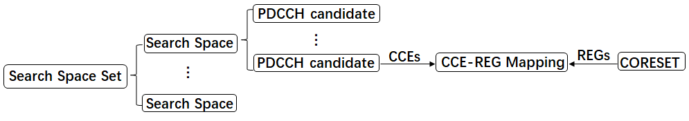
- PDCCH involves two important aspects, one is the resource for transmitting control information, that is, CORESET Control Resource SET, and the other is how the UE obtains control information in CORESET .
- The UE obtains control information by monitoring CORESET at a designated monitoring occasion (Monitoring Occasion). This process is implemented by performing a so-called blind detection ( Blind Decoding ) in the candidate set ( PDCCH Candidate ) in the configured search space ( Search Space ).
- CORESET basic unit is the REG – Resource Element Group, 1st REG correspond to 1st OFDM on symbols and 1st PRBs. CORESET included REG number is usually 6 integral multiple ( with the CCE corresponding to the size).
- PDCCH basic unit is a CCE ( Control Channel Element ). A CCE size is 6 REG and CCE is a logical resources, it requires further by interleaving (Interleaved) or interleaved (Non-Interleaved) of CCE-REG mapping the way is mapped to the CORESET resource .
PDCCH Type
There are mainly following three types of PDCCH:
- Common PDCCH Type
- Application: Common message scheduling ( RMSI, OSI, Paging, RACH MSG2/4)
- Time Domain: 1~3 Symbols (MIB or RRC configuration )
- Aggregation Level: 4/8/16
- Mapping Method: Time domain first , Interleaved
- CORESET configuration: MIB or RRC signaling
- Search Space: Common Search Space
- Group Common PDCCH Type
- Application: SFI – Slot Format Indicating and PI – Pre-emption Indicating
- Time Domain: 1~3 Symbols (MIB or RRC configuration )
- Aggregation Level: 4/8/16
- Mapping Method: Time domain first , Interleaved
- CORESET configuration: RRC signaling
- Search Space: Common Search Space
- UE-Specific PDCCH Type
- Application: User-level data scheduling and power control information scheduling
- Time Domain: 1~3 Symbols (RRC configuration )
- Aggregation Level: 1/2/4/8/16
- Mapping Method: Time domain priority, Interleaved/Non-Interleaved
- CORESET configuration: RRC signaling
- Search Space: UE-Specific Search Space
DCI Processing
The physical layer processing sequence for PDCCH channel (DCI) is shown in following picture.
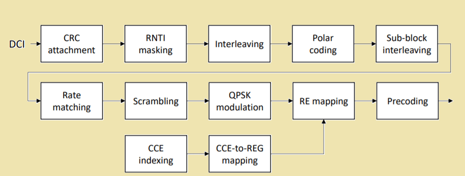
- Step 1 – Payload and padding: If the size of the DCI format is less than 12 bits, a few zero padding bits will be appended until the payload size equals 12 bits
- Step 2 – CRC Attachment: A 24-bits CRC is calculated and appended to the payload. The CRC allows the UE to detect the presence of errors in the decoded DCI payload bits.
- Step 3 – RNTI Masking: After the CRC is attached, the last 16 CRC bits are masked with the a radio network temporary identifier (RNTI). Using the RNTI mask, the UE can detect the DCI for its unicast data and distinguish sets of DCI with different purposes that have the same payload size.
- Step 4 – Interleaving: The CRC attached bits are then interleaved to distribute the CRC bits among the information bits. The interleaver supports a maximum input size of 164 bits. DCI without CRC can have at most 140 of payload bits.
- Step 5 – Polar Coding: The bits are then encoded by the Polar encoder to protect the DCI against errors during transmission.
- Step 6- Sub-block Interleaver and Rate Matching : The Polar encoder output is processed using a sub-block interleaver and then rate matched to fit the allocated payload resource elements (REs) of the DCI.
- Step 7 – Scrambling: The payload bits of each DCI are separately scrambled by a scrambling sequence generated from the length-31 Gold sequence. The scrambling sequence is initialized by the physical layer cell identity of the cell or by a UE specific scrambling identity and a UE specific cell RNTI (C-RNTI).
Step 8 – Modulation: After the scrambled DCI bit sequence is QPSK modulated - Step 9 – CCE Indexing and CCE to RE mapping: with QPSK modulation, a CCE contains 54 payload REs and therefore can carry 108 bits. This requires the output size of the rate matching block to be 𝐿 ⋅ 108, where 𝐿 is the associated AL. Based on the channel
environment and available resources, the gNB can adaptively choose a proper AL for a DCI to adjust the code rate - Step 10 – Resource Mapping: The complex-valued modulation symbols are mapped to physical resources in units referred to
as control channel elements (CCEs). Each CCE consists of six resource element groups (REGs), where a REG is defined as one PRB in one OFDM symbol which contains nine REs for the PDCCH payload and three demodulation reference signal (DMRS) REs. For each DCI, 1, 2, 4, 8, or 16 CCEs can be allocated, where the number of CCEs for a DCI is denoted as aggregation level (AL).
DCI Formats
- Uplink Transmission (PUSCH scheduling)
- DCI Format 0_0: Fallback DCI, indicating PUSCH scheduling
- DCI Format 0_1: Indicate PUSCH scheduling
- Downlink Transmission (PDSCH scheduling)
- DCI Format 1_0: Fallback DCI, indicating PDSCH scheduling, the scheduler in the common messaging eg. Paging, RMSI scheduling state transition ( eg BWP switch ) used
- DCI Format 1_1: Indicate PDSCH scheduling
- Others
- DCI Format 2_0: Slot Format Indicating
- DCI Format 2_1: Indicate in which PRB and OFDM symbols the UE does not map data
- DCI Format 2_2: PUSCH and PUCCH power control commands
- DCI Format 2_3: SRS power control command
Related Post
- 5G NR Reference Signals (DMRS, PTRS, SRS and CSI-RS)
- 5G NR Sounding Reference Signal (NR-SRS)
- 5G NR Cyclic Prefix (CP) Design
- 5G NR Quasi-Colocation Concept, Types and Application
- 5G NR CORESET – Control Resource Set