5G RLC – UM Mode Data Transmission
In 5G NR, RLC has 3 different modes of operations TM, UM and AM and each of the mode can transmit and receive data, serving different logical channels as per their requirement. This post provides an overview of RLC UM Mode data transmission.
RLC UM Mode Characteristics
- Buffering done both at Transmission and Reception
- Segmentation done at TX and Reassembly at RX
- No Feedback mechanism is required ACK/NACK for RLC PDU
- RLC UM Mode is used for DRBs
- SN Size in UM (6,12) bits
- UM RLC Segment PDU is associated with SN
- UM RLC Complete PDU is not associated with SN
- 1 RLC SDU = 1 RLC PDU
RLC Entity in UM-Mode (Un-Acknowledged Mode)
Figure below depicts, the functionality of RLC entity in UM-mode. As shown, compared to TM mode, RLC entity in UM does more functions. There is no feedback mechanism done in this mode.
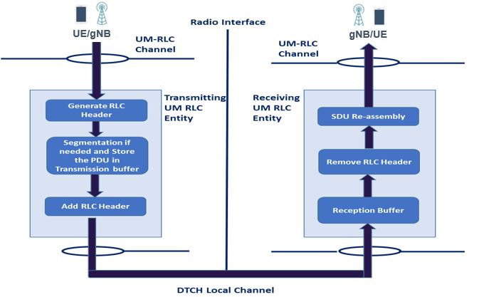
- Transmission side functionalities include
- Segmentatione. splitting of big chunk of RLC SDU (PDCP PDU) into multiple small chunk as per MAC grant and Modify RLC Header according to the segmentation done.
- Buffering of rest of the segmented RLC PDUs to transmit in next TTI
- Add the RLC header.
- Reception side functionalities include
- Remove the RLC Header
- Buffering of the received segmented data for Re-assembly.
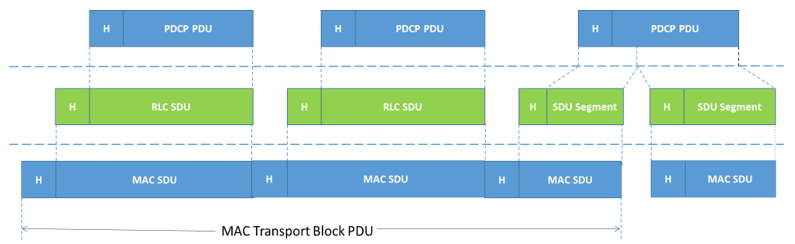
How Data Transfer happens through RLC ?
RLC entity receives/sends PDCP PDUs (i.e. RLC SDUs) from/to PDCP layer and sends/receives RLC PDUs to/from its peer RLC entity via MAC & PHY layers.
- PDU is output of a layer
- SDU is input to a layer
What is PDU Transmission Order ?
In, RLC UM mode following order is considered for PDU transmission.
- Segmented PDU
- Complete PDU
![]()
The number of RLC PDU is transmitted according to the MAC TB size. If the MAC TB size is not sufficient enough to transmit the Complete RLC PDU, then the RLC PDU is segmented.
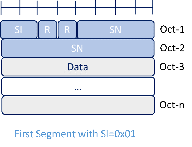
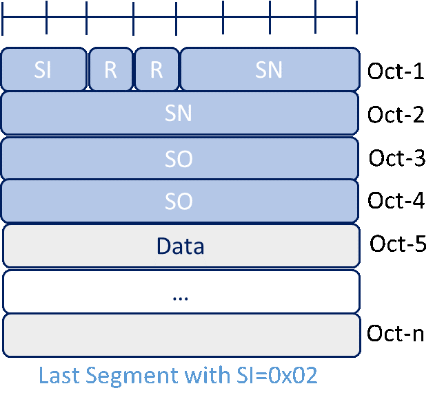
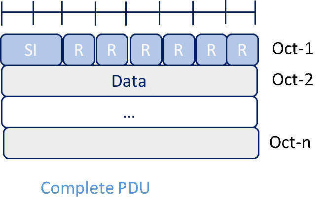
- SI: The SI field indicates whether an RLC PDU contains a complete RLC SDU or the first, middle, last segment of an RLC SDU.
- SO: Segment Offset ( Only for Middle, Last Segment)
Receive & Reassembly
In figures below, SN(5~8) lost in t1. RxNextReassembly is updated only after the t2 duration, till that time it waits for HARQ retransmission or the pending segments from UE. Post expiry of t2, RxNextReassembly is updated.
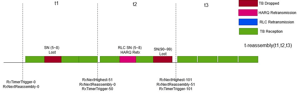
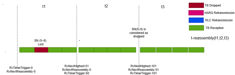
Following is the timers definition for receive and assembly:
- RxTimerTrigger: This state variable holds the value of the SN following the SN which triggered t-Reassembly
- RxNextHighest: This state variable holds the value of the SN following the SN of the UMD PDU with the highest SN among received UMD PDUs. It serves as the higher edge of the reassembly window.
- RxNextReassembly: This state variable holds the value of the earliest SN till which all the SNs are considered as received or lost.
Article Submitted By:

Mangala Jaji has about 15 years of experience in 4G, 5G System development and currently working as Architect System-Software Sasken Technologies Ltd, India. She has completed her engineering in computer Science, from Karnatak University, India.

Prerit Jain has about 15 years of experience in 4G, 5G System development and currently working as Sr. Member of Technical Staff, Altiostar Networks Inc. He completed his Bachelors of Technology from NSIT, Delhi. from India.
References:
- 3GPP 38.322 – Radio Link Control (RLC) protocol specification (Release 15)
- 3GPP 38.306 – User Equipment (UE) radio access capabilities
Related posts


