5G NR SS-RSRP Value Measurement Mapping
UE does measurement of SS-RSRP and use it for cell selection, cell reselection, power control, mobility procedures and beam management procedures. RSRP measurement generated and reported at both Layer 1 (Phy) and Layer 3 (RRC). For example, a UE can measure SS-RSRP at Layer 1 when sending CSI to the gNB and provides results at Layer 3 when sending Measurement Reports.
UE is allowed to use measurements from the PBCH-DMRS when generating SS-RSRP results. The DMRS and SS-Signal are transmitted with equal power so results can be averaged directly. When UE is measuring SS-RSRP for Layer 1 reporting, then a UE can be configured to use CSI-RS measurements as an additional input. CSI-RS may have a different transmit power compared to the SS-Signals and PBCH DMRS. The gNB provides offset information to the UE so it can be taken into account during the measurement procedure.
SS-RSRP Characteristics
- SS-RSRP is the average power received from a single Resource Element allocated to the SS-Signal
- The average is calculated using linear units in mWatts instead of dBm
- Power is measured on the energy received during the useful part of the symbol only and does not include cyclic prefix part
- For FR 1, measurement is performed at the UE antenna connector, assuming that the UE has a single antenna clement per receive path instead of an antenna array
- For FR 2, the measurement is performed based upon the combined signal strength from all antenna elements belonging to a single receive path, assuming UE has an antenna array for each receive path
- These measurement are filtered at Layer 1 and Layer 3
- SS-RSRP Layer 1 measurements are useful for procedures for beam management procedures which require the UE to rapidly switch between beams
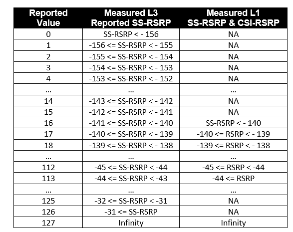
- 3GPP specification 38.133 specifies the mappings between the reported and measured values for Layer 1 and Layer 3 RSRP
- As per 3GPP specifications the min. RSRP defined for LTE is -140 dBm but the value is decreased to -156 dBm to cater for the coverage performance for eMTC applications and max. RSRP for LTE is -44dBm increase to -31 dBm to account beamforming gain at UE
Layer 1 filtered SS-RSRPP
- Layer 1 filtering is done to remove the impact of noise
- Layer 1 RSRP has a smaller reporting range compared than the Layer 3 RSRP
- A UE is configured to report Layer 1 SS-RSRP if reportQuantity within CSI-ReportConfig is set to ‘ssb-Index-RSRP’.
- Layer 1 measurements are ‘beam level’ rather than ‘cell level’ which means that each SS-RSRP result is linked to a specific SS/PBCH Block
- The RSRP value is signaled using 7 bits payload and mapping is shown in following Table
- Layer 1 SS-RSRP or CSI-RSRP can be represented from 16 (– 140dBm) to 113 (-44dBm)
Layer 3 filtered SS-RSRPP
- Layer 3 filtering is done to remove fast fading and reduce short term variations in the measurement results
- SS-RSRP Layer 3 measurements are useful for handover procedures
- The max Layer RSRP is defined as -31dBm and min. as -156dBm
- The full RSRP range have 128 entries ( -31 dBm to -156 dBm) can be represented with 7 bits
- Layer 3 measurements can be either ‘beam level’ or ‘cell level’ and can be reported to the gNB in Measurement Report message
- Layer 3 measurements, the gNB provides the UE with an SS/PBCH Block Measurement Timing Configuration
Calculating RSRP with Example:
- Reported Value= 15
- Actual RSRP Value for Layer 3 SS-RSRP= 157 – 15 = -142 dBm
Reference:
- 3GPP TS 38.215: 5G NR; Physical layer measurements
- 3GPP TS 38.213:5G NR; Physical layer procedures for control channels
- 3GPP TS 38.214: 5G NR; Physical layer procedures for data channels
Related Post:
- 5G NR Measurements: RSRP, RSSI, RSRQ and SINR
- 5G NR RSRQ Measurement and Mapping
- 5G NR RRM Measurement Requirements
- 5G NR Measurement – Serving Cell and Neighbor Cell
- 5G NR Measurement Events
- 5G NR Measurement Configuration: Meas Object, Report Config, Meas ID
- 5G NR Measurement Gap Configuration


