Optical Fiber Link Budget Calculation
Fiber optic networks is very basic form of terrestrial broadband transmission platform which is capable to delivers multimedia services such as voice, video and data to business and residential users. Originally, optical fiber was used to carry long-haul services across the continents because it’s extensive bandwidth offered with future-proof expansion opportunities. With the continued demand from emerging technology such as VoIP, IPTV and HDTV,4G and 5G access network infrastructure is under extreme pressures to facilitate increasing transmission capacity and functionality.
Due to its superior transmission capability over copper transmission, optical fiber is migrating into the metropolitan and local area networks (MAN and LAN) and even to the end user with Fiber to The Home (FTTH) technologies.
Basic of Fiber Optic Links (FOL)
In Teleports and Earth Stations, critical satellite transmission infrastructure is supported by off-air up and down links that are increasingly being formed by using optical fiber. Fundamentally the end to end design of a fiber optic link also sometimes called as a FOL. FOL is very straight forward comprising a transmitter, optical fiber with connectors and a receiver.
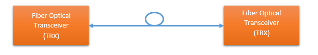
These elements enables information to be transported between two points using optical fiber. A transmitter is consist of an electo-optical device that converts electrical information into light and receiver is consist of an opto-electrical devices that reconverts light back into electrical information performs the necessary conversion processes in order to transport information over optical fiber using light. To understand the contribution the FOL on the overall transport service performance it is useful to consider the so-called ‘fiber optic link budget’
Fiber Optic Link Budget
The FOL budget provides the quantitative performance information to Network Design Engineers . The FOL budget is determined by computing the FOL power budget and overall link gain.
Fiber Optic Link Gain
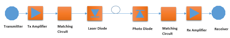
FOL link gain is a sum of gains and losses contributed by the different elements of the FOL as shown in above figure. Gains and losses contributed by the Tx, Rx, optical fiber and connectors, as well as any additional in-line components such as splitters,combiners, multiplexers ant splices etc., must be taken into accounts while computing the link loss budget. In the case of a simple point-to-point link depicted in figure above, with matched components, the link gain (G) is expressed as:-
Gain = T + R – 2LO ……………………………………………………………………………………………… (i)
Where T is the gain of the Tx, R is the gain of the Rx, and LO is the insertion loss to the fiber link. Note the factor of two in this last optical term, meaning that for each dB optical loss there is a corresponding 2dB RF loss.
To calculate LO (insertion loss) dB loss/km due to fiber and connection loss information is required. For exampe we can take a standard corning SMF28 single mode fiber which has an insertion loss 0.2dB/km at 1310nm and 0.15dB/km at 1550nm. Optical connectors such as FC/APC typically have an insertion loss of 0.25dB. Optical splices introduce a further 0.25dB loss. .
Output Noise Power
The output noise power of an analogue FOL must also be considered when quantifying the overall link budget. The measured output noise power is defined as:-
Output Noise Power = ONF + 10*log10*(BW) ………………………………………………………………. (ii)
Where ONF (Optical Noise Floor) is the noise output of the link on its own, defined in a bandwidth of 1Hz, and BW is the bandwidth of the service transported over fiber. In practices, the Noise Figure (NF) is used to define the noise performance of the fiber optic link and is related to the output noise floor as follows:-
Optical Noise Floor = -174dBm + NF + G ………………………………………………………………. (iii)
-174dBm, is the noise contribution from an ideal 1 ohm resistive load at zero degrees Kelvin temperature.
From equation (ii), measured output noise power is given as:-
Output Noise Power = -174dBm + NF + G + 10*log10*(MBW) ………………………………………………. (iv)
Practical Example
Consider a typical Fiber optical installation has noise Figure of 19dB and FOL gain attributes (Gain +Loss) about 20 dB. The system bandwidth can be assumed 25 MHz.
Substituting these values into equation (iii) gives
Optical Noise Floor= -174dBm + 19dB + 20dB
Optical Noise Floor = -135dBm
Total Output Noise Power of the FOL can be calculated by considering the transmitted service bandwidth Total Output Noise Power of the FOL to be determined from equation (iv).
Therefore the Output Noise Power is:- = -135 dBm + 10*log10*(25000000) = -135 dBm + 73 dB
= -62 dBm