LTE Overview
LTE (Long Term Evolution) or the E-UTRAN (Evolved Universal Terrestrial Access Network), introduced in 3GPP R8, is the access part of the Evolved Packet System (EPS). The main requirements for the new access network are high spectral efficiency, high peak data rates, short round trip time as well as flexibility in frequency and bandwidth.

Figure 1
GSM was developed to carry real time services, in a circuit switched manner as shown blue in figure 1, with data services only possible over a circuit switched modem connection, with very low data rates. The first step towards an IP based packet switched as shown in green in figure 1 solution was taken with the evolution of GSM to GPRS, using the same air interface and access method, TDMA (Time Division Multiple Access).
To reach higher data rates in UMTS (Universal Mobile Terrestrial System) a new access technology WCDMA (Wideband Code Division Multiple Access) was developed. The access network in UMTS emulates a circuit switched connection for real time services and a packet switched connection for datacom services (black in figure 1). In UMTS the IP address is allocated to the UE when a datacom service is established and released when the service is released. Incoming datacom services are therefore still relying upon the circuit switched core for paging.
The Evolved Packet System (EPS) is purely IP based. Both real time services and datacom services will be carried by the IP protocol. The IP address is allocated when the mobile is switched on and released when switched off.
The new access solution, LTE, is based on OFDMA (Orthogonal Frequency Division Multiple Access) and in combination with higher order modulation (up to 64QAM), large bandwidths (up to 20 MHz) and spatial multiplexing in the downlink (up to 4×4) high data rates can be achieved. The highest theoretical peak data rate on the transport channel is 75 Mbpsin the uplink, and in the downlink, using spatial multiplexing, the rate can be as high as 300 Mbps.

Figure 2
The LTE access network is simply a network of base stations, evolved NodeB (eNB), generating a flat architecture (figure 2). There is no centralized intelligent controller, and the eNBs are normally inter-connected viathe X2-interface and towards the core network by the S1-interface (figure 2). The reason for distributing the intelligence amongst the base-stations in LTE is to speed up the connection set-up and reduce the time required for a handover. For an end-user the connection set-up time for a real time data session is in many cases crucial, especially in on-line gaming. The time for a handover is essential for real-time services where end-users tend to end calls if the handover takes too long.
Another advantage with the distributed solution is that the MAC protocol layer, which is responsible for scheduling, is represented only in the UE and in the base station leading to fast communication and decisions between the eNB and the UE. In UMTS the MAC protocol, and scheduling, is located in the controller and when HSDPA was introduced an additional MAC sub-layer, responsible for HSPA scheduling was added in the NB.
The scheduler is a key component for the achievement of a fast adjusted and efficiently utilized radio resource. The Transmission Time Interval (TTI) is set to only 1 ms.
During each TTI the eNB scheduler shall:
- Consider the physical radio environment per UE. The UEs report their perceived radio quality, as an input to the scheduler to decide which Modulation and Coding scheme to use. The solution relies on rapid adaptation to channel variations, employing HARQ (Hybrid Automatic Repeat Request) with soft-combining and rate adaptation.
- Prioritize the QoS service requirements amongst the UEs. LTE supports both delay sensitive real-time services as well as datacom services requiring high data peak rates.
- Inform the UEs of allocated radio resources. The eNB schedules the UEs both on the downlink and on the uplink. For each UE scheduled in a TTI the user data will be carried in a Transport Block (TB). DL there can be a maximum of two TBs generated per TTI per UE – if spatial multiplexing is used. The TB is delivered on a transport channel. In LTE the number of channels is decreased compare to UMTS. For the user plane there isonly one shared transport channel in each direction. The TB sent on the channel, can therefore contain bits from a number of services, multiplexed together.
To achieve high radio spectral efficiency as well as enable efficient scheduling in both time and frequency domain, a multicarrier approach for multiple access was chosen by 3GPP. For the downlink, OFDMA (Orthogonal Frequency Division Multiple Access) was selected and for the uplink SC-FDMA (Single Carrier – Frequency Division Multiple Access) also known as DFT (Discrete Fourier Transform) spread OFDMA (figure 3).

Figure 3
OFDM is a multicarrier technology subdividing the available bandwidth into a multitude of mutual orthogonal narrowband subcarriers. In OFDMA these subcarriers can be shared between multiple users. The OFDMA solution leads to high Peak-to-Average Power Ratio (PAPR) requiring expensive power amplifiers with high requirements on linearity, increasing the power consumption for the sender. This is no problem in the eNB, but would lead to very expensive handsets. Hence a different solution was selected for the UL. As illustrated in figure 3, the SC-FDMA solution generates a signal with single carrier characteristics, hence with a low PAPR.
To enable possible deployment around the world, supporting as many regulatory requirements as possible, LTE is developed for a number of frequency bands – E-UTRA operating bands- currently ranging from 700 MHz up to 2.7GHz. The available bandwidths are also flexible starting with 1.4 MHz up to 20 MHz. LTE is developed to support both the time division duplex technology (TDD) as well as frequency division duplex (FDD). In R8 there are 15 bands specified for FDD and eight bands for TTD. In R9 four bands were added for FDD. Also added in R9 were for example Multimedia Broadcast Multicast Service (MBMS), and Home eNB (HeNB), see figure 4. MBMS is used to provide broadcast information to all users, for example advertisement, and multicast to a closed group subscribing to a specific service, e.g. streaming TV. HeNBs are introduced mainly to provide coverage indoors, in homes or offices.The HeNB is a low power eNB that will be used in small cells – femto cells. Normally it will be owned by the customer, deployed without any network planning and connected to the operators EPC (Evolved Packet Core).
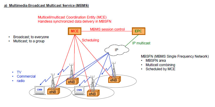
Figure 4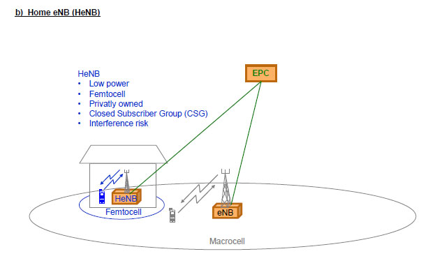
Related Posts
- LTE Frame Structure both for FDD and TDD
- MASTER INFORMATION BLOCK (MIB)
- PLMN Selection in LTE
- LTE Cell Camping and Selection Procedure


