LTE TDD Special Subframe and Its significance for Cell Size
Long Term Evolution (LTE) supports both FDD and TDD Duplex mode. The major difference in TDD and FDD is that in TDD system a single frequency is shared in time domain between Uplink and Downlink where as in FDD separate frequencies are used for Uplink and Downlink transmission. A TDD frame structure is shown in below figure. 10 mili second radio frame consists of Downlink subframe, Uplink subframe and Special subframe. 
- In TDD there are about 7 frame configurations, based on different DL/UL partition. Downlink/Uplink ratio can vary from 1/3 (Frame configuration = 0) to 8/1 (Frame configuration = 1). An operator can choose a specific TDD configuration depending on the service requirements
- Frame always starts with a Downlink subframe, used for advertising the frame descriptor information i.e. PCFICH and PDCCH. UE hence learns the frame structure in the subframe.
- 3rd frame is always used for Uplink transmission
- When switching from Downlink to Uplink, there is need for a Special subframe and no Special subframe is need when switching from Uplink to Downlink.
 Special subframe Details
TDD duplex mode needs to switch transmission from Downlink to Uplink and Uplink to Downlink, hence Special subframe is required for switching the transmission from Downlink to Uplink. In TDD, there are two periodicity frame one with 5ms periodicity and another with 10 ms periodicity. Special subframe is introduced at subframe #1 and subframe #6 and each half frame of 5ms carries one special subframe in case of 5ms periodicity subframe. Whereas 10 ms periodicity frame has only one Special subframe as subframe #1 . A Special subframe has three past DwPTS(Downlink Pilot Time Slot),GP (Guard Period) and UpPTS (Uplink Pilot Time Slot) and all of these have configurable lengths while the sum of the lengths has to be 1 ms or 14 symbols.
- DwPTS is considered as a “normal” DL subframe and carries reference signals and control information as well as data for those cases when sufficient duration is configured. It also carries PSS.
- GP is used to control the switching between the UL and DL transmission. Switching between transmission directions has a small hardware delay for both UE and eNodeB and needs to be compensated by GP. GP has to be large enough to cover the propagation delay of DL interferes. Its length determines the maximum supportable cell size.
- UpPTS is primarily intended for sounding reference signals (SRS) transmission from UE. Mainly used for RACH transmission.
Why We need Guard Period for DL to UL?
The guard period for switching from DL to UL is required because all UL transmissions from multiple UEs must arrive at the same time at eNB receiver. However, guard period from UL to DL switching is not required because the eNB is the only entity transmitting. Also, the timing advance serves as a natural cushion for UE for seamless transition from UL to DL. As to the concern why eNodeB does not require time for RX-TX or UL-DL switching, because of high-end radio architecture and processing capabilities of eNodeB allows it to switch from RX-TX mode without any delay.
How Special subframe configuration impact Cell Size?
In TDD , there are 9 special subframe configuration, each have different number of OFDM symbols for DwPTS,GP and UpPTS. Special subframe guard period impact the size of cell, it represent how much propagation delay it can compensate. Longer guard period can compensate more propagation delay result a longer cell size.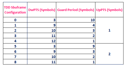
Cell Size Calculation and Cell size for different Special subframes:
Lets take Special Subframe (SSP) o which has 10 OFDM symbol for Guard Period. Convert these 10 OFDM symbol to equivalent time which (10/14 )/1000= 0.0007 sec . RF signal travel with velocity of light C=300000 Km/sec.
- Distance= Velocity*time = 300000 x 0.0007 = 210 Km >>> Mind that this is round trip distance
- cell radius is half of RTD=210/2 = 105 Km which is ~ 100 Km.
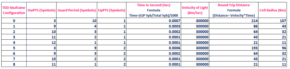
So considering this table the Special subframe configuration 0 provide the largest cell of about 100 Km cell radius while Special subframe configuration 4 and 8 has least cell size of about 10 Km.
Most of TDD operator prefer Special subframe 5 for long cells and Special subframe 7 for small cell because of more symbols for UpPTS and these UpPTS symbols can be utilize for RACH planning and Uplink SRS signals.
Note: The Guard Period does not alone decide the cell size, there are other important parameter like RACH Format, Transmit Power , Receiver Sensitivity,Target Cell Throughput etc play a crucial role for decide cell size, But while decide other parameter a planning Engineering need to consider the impact of TDD special subframe.
Related Posts:
- RSRP (Received Signal Received Power)
- RSSI (Received Signal Strength Indicator)
- RSRQ (Received Signal Received Quality)
- Signal to Noise Ratio
- LTE FDD System Capacity and Throughput Calculations