RF Sampling, making smaller base station for 3G, 4G, 5G Systems
“RF sampling” is the technology of digitizing an RF signal with an ADC directly, without an analog frequency conversion to a lower IF (intermediate frequency) or baseband (Zero IF) before the signal is converted from analog to digital.
An RF sampling ADC can replace a radio signal path subsystem of mixers, LO synthesizers, intermediate frequency amplifiers and filters, and sometimes multiple ADCs, reducing bill of materials, cost, design time, size, weight, and power, while increasing the software programmability and flexibility of the system.
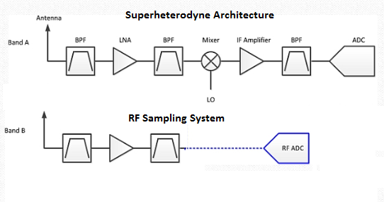
In a heterodyne receiver, the input signal, which resides at an RF frequency, is down-converted to a lower intermediate frequency (IF). It is then digitized prior to digital filtering and demodulation.
It consists of bandpass filters (BPFs), a lownoise amplifier (LNA), mixer and local oscillator (LO), an IF amplifier, and ADC anti-aliasing filter (AAF). In a direct-conversion receiver, the RF-sampling ADC replaces the signal chain from the mixer, which greatly simplifies the overall receiver design.
System designers who are considering switching from Heterodyne to RF-sampling need to solve following primary challenges:
- Receiver sensitivity
- Radio performance in presence of in-band interferer
- Filter requirements for out-of-band blocker
Receiver sensitivity
Receiver sensitivity is the lowest power level at which the receiver can detect an RF signal and demodulate data. One of the major parameter that impact the sensitivity is the noise figure of the receiver chain. In heterodyne architecture, there is enough gain before the ADC in the signal chain so that ADC noise figure does not impact much to the sensitivity.
As we all know that, the most common way to improve an ADC’s noise figure is to add an amplifier before the ADC.
So in RF sampling system, there is a need of LNAs before the ADC to reduce the overall noise figure of the chain.
In-band blocker
In-band interferers manage to get within the front-end filter passband. The receiver in-band blocking performance is a measure of how well the receiver can demodulate weak signals in the presence of such an in-band interferer. Because the in-band interfere power level is high and the desired signal power level is low, so high power level of interfere may saturate the ADC or due to limited SFDR of ADC, desired signal may get lost in noise. Generally, low order harmonics cause reduction in SFDR of ADC, which can be avoided by a perfect frequency plan.
The phase noise of the sampling clock (jitter) also mixes with the interferer. So there is a need of better phase noise performance clock.
Out of band blocker
Independent of architecture, the ADC input must be protected from large, out-of-band interferers because that would either alias the in-band to exceed the ADC full scale and saturate the receiver, or generate harmonics that would overlap with a small, in-band wanted signal.
The filter design for RF-sampling systems is a little bit more relaxed when frequency planning is applied. There are no mixer images or LO spurs to worry about but low-order harmonics, or interleaving spurs of out-of-band interferers, still need to be considered
Summary
Base station designers are seeking new ways to increase radio capacity while reducing cost, size and weight. And RF sampling based architecture provide these benefits, and system designers around the world have started working on this.