IoT Device Battery Life 10 Years !!! How is it possible?
Energy is the most scarce resource for an electronics device and when someone designing it, he needs to optimize its operation so that it consumes minimum power. When a device has a regular power supply along with the battery backup, one will not be worried but in the case where the device has only battery as power source and this can not be charged regularly, then every milli watt or every joule of energy saving can benefit a lot.
When we talk about the Internet of thing devices, the requirement is set as the device consumption should be as low as much that it can last long for 10’s of years. The reason behind this stringent requirement is because of the placement of device where charging it and replacing its battery is not possible. Let us take a use case from IoT Health sector, a doctor placed an IoT sensor in patient’s body after a surgery to diagnose a critical disease to get regular observations readings, so he can not operate him again and again just to recharge or to replace the battery, in such case the device should consume minimum power as much as it can.
3GPP TR 45.820 for cellular IoT Release 13 has provided the calculation for the battery life for a NB-IoT device in chapter 7.3.6.4 with “Energy consumption evolution” and methodology to calculate in chapter 5.4 with “Energy consumption evolution methodology”.
Methodology
Energy consumption analysis is to calculate the achievable battery life for an IoT device using a specific solution. The battery capacity can be assumed as a 5WH without consideration of battery leakage.
When a device has to send an IP packet and receives an IP packet acknowledgment of that packet, it has to go through the different events and this event affects the energy consumption of the device. The figure below shows an example of Energy consumption model.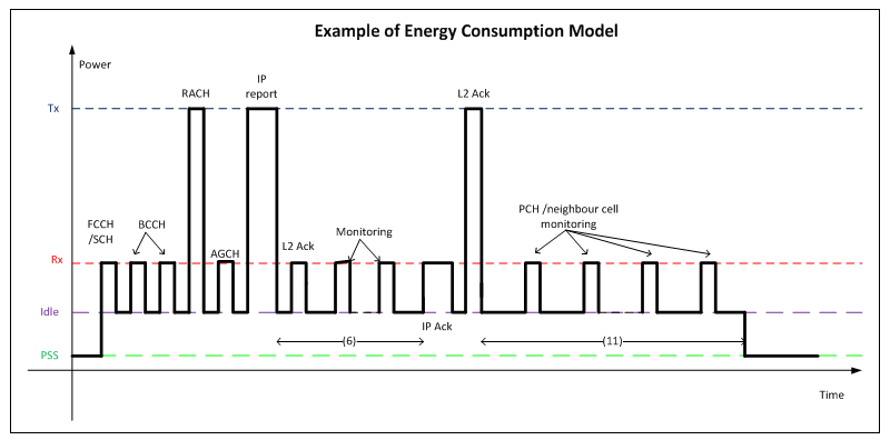
Figure #1
The events responsible for battery consumption includes scanning the broadcast channel, attempting random access to get uplink synchronization, sending & receiving IP packets, monitoring paging and control channels etc. Even when a device is in idle mode or power saving mode (PSM), it still consumes some power.
As per specification the energy consumption methodology comprises of two steps,
Step 1: Getting all key input parameters values
Step 2: Calculating battery life
Step 1: Following are the Key Input Parameters
- Battery capacity (Wh): 5
- Battery power during Tx(mW):
- Battery power for Rx (mW)
- Battery power when Idle but not in PSS (mW)
- Battery power in Power Save State (PSS) (mW) = 0.015
- Time between end of IP packet carrying “report” and start of IP packet carrying “ack” on radio (ms)= 1000
- Number of reports per day
- Rx time from PSS exit to re-entry into PSS (ms)
- Idle time from PSS exit to re-entry into PSS (ms)
- Tx time from PSS exit to re-entry into PSS (ms)
- Time from last Rx or Tx activity to entry into PSS1 (ms)= 20000
Step 2: Battery life calculation Steps
- Energy consumed per Data Report
e1 (mW×ms) = energy for Tx + energy for Rx + energy for tasks in idle
= (10) × (2) + (8) × (3) + (9) × (4)
E1 (Joules) = e1 / 1 000 000
- Energy consumed per Day
E2 (Joules) = energy consumed per report × reports per day + energy in PSS per day
= E1× (7) + (5) ×3600*24/1000
e2 (Watt Hours) = E2/3600
- Days of battery Life => D = battery energy capacity / energy consumed per day = (1)/e2
- Years of battery Life => Y = D/365
The energy consumed per day by each device is also dependent on the reporting interval and the power consumption in Power Save State (PSS) which is assumed to be [0.015] mW.
Energy Consumption Evaluation for NB-IoT Device
TR 45.820 section 7.3.6.4 provides an analysis of the device battery life that can be achieved with the NB-IoT. During the analysis following assumptions has been taken for instantaneous power consumption for the major operating modes.
| Operating Mode | Parameter | Power (mW) | Notes |
| Transmit (+23 dBm) | Integrated PA | 500 | +23 dBm with 45% PA efficiency for class B (including Tx/Rx switch insertion loss) plus 60 mW for other circuitry. |
| Transmit (+23 dBm) | External PA | 460 | +23 dBm with 50% PA efficiency for class B (including Tx/Rx switch insertion loss) plus 60 mW for other circuitry. |
| Receive | Synchronization (PSCH) | 80 | Accounts for more complex digital processing during synchronization, using FFT based cross-correlation for PSS detection. |
| Receive | Normal (PBCH, PDCCH, PDSCH) | 70 | Includes FFT based OFDM demodulation, based on a sampling rate of 240 kHz. |
| Sleep | 3 | Corresponds to maintaining accurate timing by keeping RF frequency reference active. | |
| Standby | 0.015 | Common assumption. |
Table #1
The NB-IoT protocol flow that is assumed for the energy consumption analysis is illustrated in Figure below based on the Gb core network architecture, and according to the downlink physical layer design and uplink physical layer.

Figure #2
The PDCCH interval depends on the coverage class and follows the typical configuration. Potential re-transmissions of the uplink report are shown, including an additional PDCCH reception for the MAC layer ACK associated with the uplink retransmission.
The average time taken for network synchronization and for system information reading is shown in Table below which is based on the link level simulation. The latency values indicate the total elapsed time for PSCH detection or PBCH reading, while the Rx active times indicate the time for which the radio receiver is active. It is assumed that the device has not moved to a different cell sector and that only the Primary System Information (PSI) needs to be read (so the Secondary System Information is assumed to be unchanged since the previous reception). No PSD boosting has been assumed for PSCH or PBCH.
| Coupling loss = 144 dB | Coupling loss = 154 dB | Coupling loss = 164 dB | ||||
| Latency (ms) | Rx active time (ms) | Latency (ms) | Rx active time (ms) | Latency (ms) | Rx active time (ms) | |
| PSCH | 278 | 278 | 291 | 291 | 445 | 445 |
| PBCH (PSI) | 10 | 10 | 10 | 10 | 650 | 30 |
Table #2
The selection of MCS and CBS for each PDCCH, PDSCH and PUSCH burst type at each coupling loss is shown in Table below, including the resulting burst durations.
Data bursts include a 15 byte overhead in addition to the packet size above SNDCP (4 bytes for SNDCP, 6 bytes for LLC, 2 bytes for MAC header, and 3 bytes for CRC), and the first uplink burst after RACH uses an additional 5 bytes for TLLI. No PSD boosting or adaptive power allocation has been assumed for PDCCH or PDSCH.
| Coupling loss = 144 dB | Coupling loss = 154 dB | Coupling loss = 164 dB | ||||||||
| Burst type | PHY burst size | MCS index | CBS index, #tones | Duration (ms) | MCS index | CBS index, #tones | Duration (ms) | MCS index | CBS index, #tones | Duration (ms) |
| PDCCH | 10 bytes | CC1 | – | 5 | CC3 | – | 30 | CC4 | – | 220 |
| PDSCH (29 bytes) | App ACK(29+15 = 44 bytes) | 7 | 3, #2 | 50 | 3 | 1, #4 | 100 | 0 | 1, #4 | 800 |
| PUSCH Random Access |
5 bytes | 5 | 0 | 40 | 5 | 0 | 40 | 1 | 0 | 320 |
| PUSCH Short Data (50 bytes) | Short report(50+15+5 = 70 bytes) | 9 | 3 | 40 | 6 | 7 | 320 | 3 | 15 | 1920 |
| PUSCH Long Data (200 bytes) | Long report (200+15+5 = 220 bytes) | 9 | 11 | 120 | 6 | 23 | 960 | 4 | 47 | 3840 |
| PUSCH ACK of DL data | MAC layer ACK (5 bytes) | 8 | 0 | 10 | 5 | 0 | 40 | 1 | 0 | 320 |
Table #3
The impact of re-transmissions of the uplink reports is included in the energy consumption analysis by taking account of the simulated BLER for the initial transmission of the uplink report for each scenario. This means that the energy consumption analysis takes account of the average number of retransmissions of the uplink report. The effect of BLER on channels other than PUSCH is not considered.
Results
The achievable battery life in years has been estimated as a function of reporting frequency and coupling loss, based on the above-stated assumptions. The results for an integrated PA are summarized in Table 4 and for an external PA in Table 5. In both cases, the transmit power from the device is constrained to be +23 dBm (200 mW) to ensure compatibility in terms of peak current with a wider range of battery technologies, and the frequency re-use assumption is compatible with a stand-alone deployment in a system bandwidth for the entire network of just 200 kHz (FDD).
| Battery life (years) | |||
| Packet size, reporting interval | Coupling loss = 144 dB | Coupling loss = 154 dB | Coupling loss = 164 dB |
| 50 bytes, 2 hours | 22.4 | 11.0 | 2.5 |
| 200 bytes, 2 hours | 18.2 | 5.9 | 1.5 |
| 50 bytes, 1 day | 36.0 | 31.6 | 17.5 |
| 200 bytes, 1 day | 34.9 | 26.2 | 12.8 |
Table #4
| Battery life (years) | |||
| Packet size, reporting interval | Coupling loss = 144 dB | Coupling loss = 154 dB | Coupling loss = 164 dB |
| 50 bytes, 2 hours | 22.8 | 11.5 | 2.7 |
| 200 bytes, 2 hours | 18.8 | 6.3 | 1.7 |
| 50 bytes, 1 day | 36.1 | 31.9 | 18.1 |
| 200 bytes, 1 day | 35.1 | 26.8 | 13.4 |
Table#5
The Key conclusions are :
- For all coupling losses (so up to 20 dB coverage extension compared with legacy GPRS), a 10-year battery life is achievable with a reporting interval of one day for both 50 bytes and 200 bytes application payloads.
- For a coupling loss of 144 dB (so equal to the MCL for legacy GPRS), a 10-year battery life is achievable with a two-hour reporting interval for both 50 bytes and 200 bytes application payloads.
- For a coupling loss of 154 dB, a 10-year battery life is achievable with a 2-hour reporting interval for a 50-byte application payload.
- For a coupling loss of 154 dB with 200-byte application payload or a coupling loss of 164 dB with 50 or 200-byte application payload, a 10-year battery life is not achievable for a 2-hour reporting interval. This is a consequence of the transmit energy per data bit (integrated over the number of repetitions) that is required to overcome the coupling loss and so provide an adequate SNR at the receiver
- Use of an integrated PA only has a small negative impact on battery life, based on the assumption of a 5% reduction in PA efficiency compared with an external PA.
Further improvements in battery life, especially for the case of high coupling loss, could be obtained if the common assumption that the downlink Power Spectral Density (PSD) will not exceed that of legacy GPRS was either relaxed to allow PSD boosting, or defined more precisely to allow adaptive power allocation with frequency hopping.
Reference:
- 3GPP TR 45.820 V13.1.0 (2015-11) Technical Report Cellular system support for ultra-low complexity and low throughput Internet of Things (CIoT) (Release 13)
Related Posts:
- Cat. NB1 and Cat. NB2 Devices Comparison
- Narrow Band IoT- Signalling Radio Bearers (SRBs)
- IoT Device Battey Life 10 Years !!! How is it possible? Battery Life Calculation for NB-IoT Device
- Narrow Band IoT Modem Chipset Vendors
- Samsung’s NB IOT Modem