LoRa- (Long Range) Network and Protocol Architecture & Frame Structure
LoRa is Long Range ,low data rate, low power wireless platform technology for building IoT network. It uses unlicensed radio spectrum in the Industrial, Scientific and Medical (ISM) bands to enable communication between remote sensors and gateways connected to the network Server and Application Servers.
LoRa technology is owned by a chip company – Semtech, who acquired it from another French startup – Cycleo. Semtech has formed the LoRa Alliance, which develops global standards and makes this available under a royalty free license to its members. Semtech builds LoRa Technology into its chipsets. These chipsets are then built into the products offered by our vast network of IoT partners and integrated into LPWANs from mobile network operators worldwide.
LoRa Network Architecture
LoRa Network is shown in picture below:
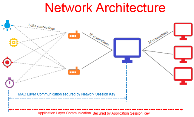
LoRa network uses a star topology in which an end node can send messages to multiple gateways that communicate with the network server. Since an end node does not belong to a specific gateway, more than one gateway can receive a message sent by an end devices. LoRa radio access technology is used in communications between an end device and the gateways. The gateways and network server are connected via standard IP connections.
- End Device: A LoRa End device is used to send small amounts of data at low frequencies over long distances. It can be utilized in various applications such as smart city, smart building, factory automation, farm automation, and logistics.
- LoRa Gateway: A LoRa gateway is a LoRa BTS receives packets from the end node via a radio link and then forwards them to the network server through the IP backhaul or 3G/4G broadband connections.
- Network Server: Network server manages the entire network. When it receives packets, it removes the redundancy of packets and performs a security check and then determines the most suitable gateway to send back an acknowledgement message.
- Application Server: A Application Server is the end server where all data sent by End Device is post processes and necessary action being taken.
LoRa Protocol Architecture
LoRa protocol specification is developed by the LoRa Alliance. The end to end network protocol architecture is shown below. LoRaWAN’s protocol consists of a MAC Layer and an Application Layer, and it operates based on the LoRa physical layer.

Frame Structure
LoRa protocol frame structure for Physical Layer, MAC Layer and Higher Layer is shown in below picture.
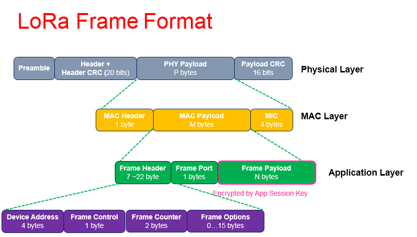
- Physical Layer Frame: At PHY layer, a LoRa frame starts with a preamble. Apart from the synchronization
function, the preamble defines the packet modulation scheme, being modulated with the same spreading factor
as the rest of the packet. Typically, the preamble duration is 12.25 Ts. The preamble is followed by a PHY Header and a Header CRC that together are 20-bits long and are encoded with the most reliable code rate of , while the rest of the frame is encoded with the code rate specified in the PHY Header. The PHY header also contains such information as payload length and whether the Payload 16-bit CRC is present in the frame. Specifically, in a LoRa network, only uplink frames contain payload CRC. PHY payload contains MAC Frame - MAC Layer Frame: The packet processed in the MAC layer consists of a MAC Header , a MAC Payload, and a Message Integrity Code (MIC). MAC header defines protocol version and message type, i.e., whether it is a data or a management frame, whether it is transmitted in uplink or downlink, whether it shall be acknowledged. MAC Header can also notify that this is a vendor specific message. In a join procedure for end node activation, the MAC Payload can be replaced by join request or join accept messages. The entire MAC Header and MAC Payload portion is used to compute the MIC value with a network session key (Nwk_SKey). The MIC value is used to prevent the forgery of messages and authenticate the end node.
- Application Layer Packet: The MAC Payload handled by the Application layer consists of a Frame Header , an Frame Port, and a Frame Payload. The Frame Port value is determined depending on the application type. The Frame Payload value is encrypted with an application session key (App_SKey). This encryption is based on the AES 128 algorithm.
Frame Header contains the following information.
- Device address which contains two parts. The first 8 bits identify the network, other bits are assigned dynamically during joining the network and identify the device in a network.
- Frame Control 1 byte for network control information, such as whether to use the data rate specified by the gateway for uplink transmission, whether this message acknowledges the reception of the previous message, whether the gateway has more data for the mote.
- Frame counter for sequence numbering
- Frame options for commands used to change data rate, transmission power and connection validation etc.
LoRa Technology Applications
- Air Pollution Monitoring
- Agriculture Processing
- Animal Tracking
- Fire Detection
- Fleet Tracking
- Home Security
- Indoor Air Quality
- Industrial Temperature Monitoring
- Assets Management
- Predictive Maintenance
- Radiation Leak Detection
- Smart Lighting
- Smart Parking
- Waste Management
- Water Flow Monitoring
References
- Lora-alliance Resource-Hub
- On the Limits of LoRaWAN Channel Access
- A Dual Key-Based Activation Scheme for Secure LoRaWAN
Related Post
- Low Power Wide Area Network (LPWAN)
- LoRa Technology, It’s Features and Application
- LoRa- (Long Range) Network and Protocol Architecture with Its Frame Structure
- LoRa – Device Activation Call Flow (Join Procedure) using OTAA and ABP
- LoRa – Device Re-activation Call Flow (Rejoin Procedure)
- LoRa Sensitivity and Link-budget Calculations

