Network Function Virtualization Architecture
NFV Architecture
Classical MNO’s network is crowded with a variety of proprietary hardware elements e.g. routers, switches, Packet Core nodes, and Access nodes. Whenever it wants to launch a new network service it often requires yet another hardware element. Finding the space and power to accommodate this new hardware is becoming increasingly difficult, compounded by the increasing costs of energy, capital investment challenges and the rarity of skills (necessary to design, integrate and operate increasingly complex hardware-based appliances).
Moreover, hardware-based appliances have an end of life i.e. 5 years or 10 years, which puts an additional burden of a procure-design-integrate-deploy cycle with little or no revenue benefits on the service provider. Hardware life cycles are becoming shorter as technology and services innovation accelerates, slow down the roll out of new revenue earning network services and restricting innovations in a network-centric connected world.
NFV Definition
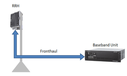
The Network Functions Virtualization (NFV) is a network architecture or concept that utilizes the IT technology fundamentals to virtualize entire network node functions onto industry standard high volume servers, switches and storage, which could be located in Data centers or centralized locations. Network Nodes are in the end user premises to create communication services and illustrated in Figure #1.
It involves implementing network functions in a software that can run on a range of industry standard server hardware, and that can be moved to, or instantiated in, various locations in the network as in when required, without the need to install new hardware equipment.
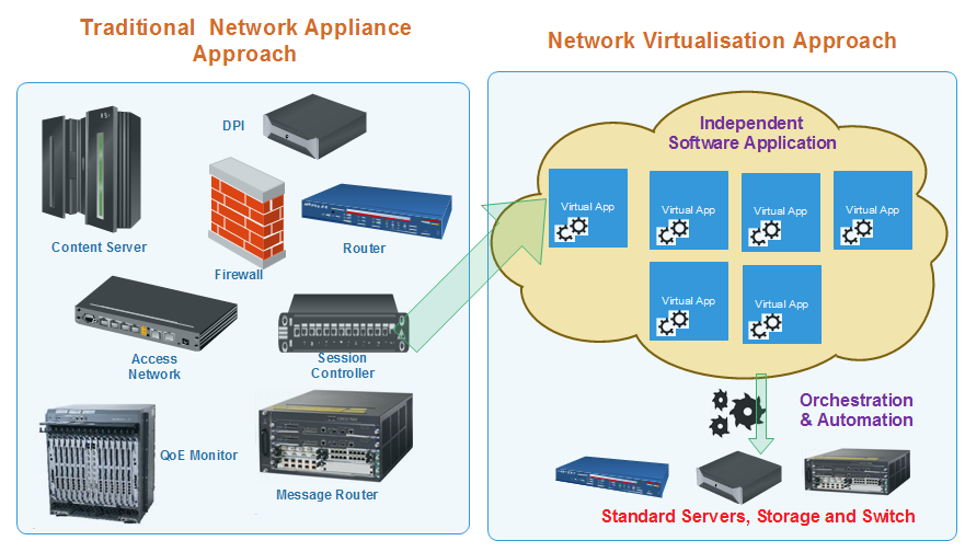
Figure #1
ETSI NFVI Architecture
ETSI has created different standards, the one provided below is one of the most important, which illustrates how the NFVI help us to decouple the hardware and software.
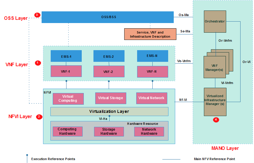
Figure #2
NFV blocks are shown in Figure #2. It can be divided into four layers:
- Virtualization Network Function (VNF) Layer
- NFV Infrastructure (NFVI) Layer
- Operation Support Subsystem (OSS) Layer
- Management and Orchestration (MANO) Layer
1. Virtualization Network Function (VNF) Layer
It has two subsections Virtual Network Function (VNF) and Element Management System (EMS)
A Virtual Network Function (VNF) is the basic block in NFV Architecture. It virtualized network function. e.g. when a router is virtualized, we call it Router VNF and when a base station is virtual we call it as base station VNF, similarly, it can be DHCP server VNF and Firewall VNF. Even when one sub-function of a network element is virtualized, it is called VNF. For example in Evolved Packet Corer case, various sub-functions like MME, Gateways, and HSS can be separate VNFs which together function as virtual EPC.
A VNFs are deployed on Virtual Machines (VMs). A VNF can be deployed on multiple VMs where each VM hosts a single function of VNF. However, the whole VNF can also be deployed be on a single VM as well.
Element Management System (EMS) is responsible for the functional management of VNF. The management functions include Fault, Configuration, Accounting, Performance and Security Management. An EMS may manage the VNFs through proprietary interfaces. There may be one EMS per VNF or one EMS that can manage multiple VNFs. EMS itself can be deployed as Virtual Network Function (VNF).
2. NFV Infrastructure (NFVI) Layer
NFV Infrastructure is the totality of hardware and software components which build up the environment in which VNFs are deployed, managed and executed. NFV infrastructure physically can span across several locations, the network provides connectivity between these locations to be part of NFV infrastructure.
NFV Infrastructure includes following
- Hardware Resources
- Virtualization Layer
- Virtual Resources
From VNF point of view, the virtualization layer and hardware resources shall be a single entity providing it the desired resource.
Hardware Resource includes computing, storage and network the provides processing, storage and connectivity to VNFs through virtualization (hypervisor) layer. Computing and storage resources are commonly used in a pool.The network resource comprises of switching functions e.g. router, wired or wireless network.
Virtualization Layer also known as a hypervisor, it abstracts the hardware resources and decouples the VNF software from the underlying hardware to ensure a hardware independent life cycle for VNFs. It is mainly responsible for following:
- Abstracting and logically partitioning physical resources, commonly as hardware abstraction layer
- Enabling the software to implement the VNF to use the underlying Virtualization Infrastructure
- Providing the virtualised resources to VNF, so that latter can be executed
The virtualization layer in middle ensures VNFs are decoupled from hardware resource and therefore software can be deployed on different physical resources.
Virtual Resources
Virtualization layer abstracts the computing, storage, and network from hardware layer make available as Virtual Resources.
3. OSS/BSS Layer
OSS/BSS refers to OSS/BSS of an operator. OSS deals with network management, fault management, configuration management and service management. BSS deals with customer management, product management and order management etc.
In the NFV architecture, the decoupled BSS/OSS of an operator may be integrated with the NFV Management and Orchestration using standard interfaces.
4. Management and Orchestration (MANO) Layer
Management and Orchestration Layer is also abbreviated as MANO and it includes three components:
- Virtualized Infrastructure Manager(s)
- VNF Manager(s)
- Orchestrator
MANO interacts with both NFVI and VNF layer. MANO layer manages all the resources in the infrastructure layer, it also creates and deletes resources and manages their allocation of the VNFs.
Virtualized Infrastructure Manager (VIM)
It comprises the functionalities that are used to control and manage the interaction of a VNF with computing, storage and network resources under its authority, as well as their virtualisation. Virtualised infrastructure Manager performs the following:
- Inventory of software, computing, storage and network resources dedicated to NFV infrastructure
- Management of infrastructure resource and allocation e.g. increasing the VMs, increasing energy efficiency etc.
- Allocation of VMs on hypervisors, Compute resources, storage, and relevant network connectivity
- Root cause analysis of performance issues from the NFV infrastructure perspective
- Collection of infrastructure fault information
- Collection of information for capacity planning, monitoring, and optimization
VNF Manager is responsible for VNF life cycle management which includes installation, updates, query, scale up/down and termination. A VNF manager may be deployed for each VNF or a single VNF manager may be deployed to serve multiple VNFs.
Orchestrator is in charge of the orchestration and management of NFV infrastructure and software resources and realizing network services
There is one more independent block know as Service, VNF and Infrastructure apart from above building blocks.This includes data-sets that provide information regarding VNF deployment template, VNF forwarding graphs, service related information and NFV infrastructure information models.
Related Posts:
- Virtual Network’s Most Common Definitions
- Network Function Virtualization (NFV) Architecture
- Virtual Network Function (VNF) Definition, Architecture and Design
- OpenStack, OpenStack Component and Its Deployment Models
- NFV Management and Orchestration [MANO] Key Performance Indicators [KPIs]