X2 Handover Call Flow in 4G LTE
Introduction
In handover process a UE sessions are transferred from the current serving cell to another one while it is moving towards a neighbor cell and UE ends up with a new connection with the new eNodeB.
In handover procedure, its the serving eNodeB determines whether to initiate the handover procedure or not based on RRC Measurement Reports received from the UE periodically. When handover decision is to taken, the serving cell eNB also chooses the target eNodeB cell from its neighbor list and the type of handover, i.e., X2 handover or S1 handover. If X2 link is established with the target eNodeB and it is available at the moment, the source eNodeB performs X2 handover, Otherwise it decide to perform the S1 handover.
X2 Handover Scenario
The X2 handover call flow involves signaling exchange among Source eNodeB, Target eNodeB and the MME. The following diagram shows the conceptual flow.
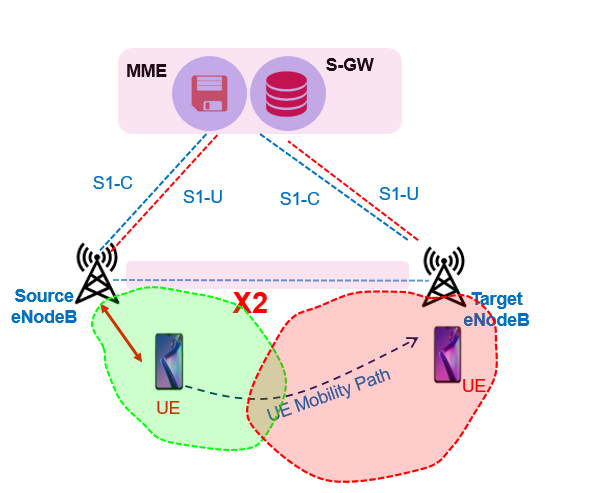
- UE periodically sends RRC Measurement Reports (MRM) to the source eNodeB
- The source eNodeB decides X2 handover and send X2 Handover Request to the target eNodeB.
- The Target eNodeB establishes uplink S1 bearer with the same S-GW with which the source eNodeB has been connected. The source eNB establishes a direct tunnel with the target eNB.
- UE handover is successfully performed. Henceforth, the buffered data is transferred to the UE from the target eNodeB
- The target eNodeB notify the S-GW that the handover has been completed successfully. The S-GW establishes downlink S1 bearer with the target eNodeB
- The S-GW switches the data path from the source eNodeB to the target eNodeB and releases the old S1 bearer
E2E X2 Handover Call Flow
Following figure show the end to end call flow for X2 Handover in 4G E-UTRA.
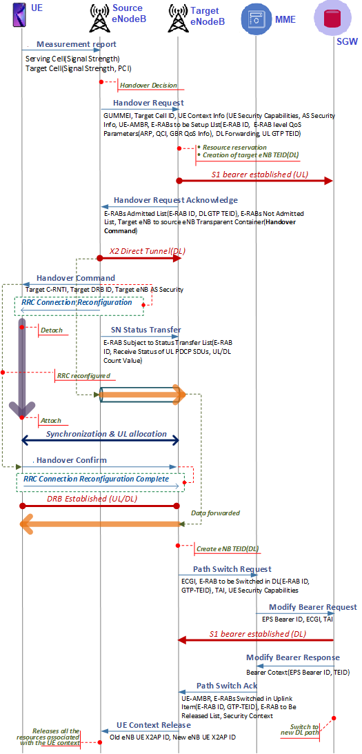
- UE periodically sends a measurement report (Meas Reports) to the serving eNodeB. These measurement reports are intended for the UE to find out the best cell to inform the eNodeB. The measurement report may contain the list of neighbor cells, neighbor cells signal strength and serving cells signal strength
- Based on the received Meas Report, the serving eNodeB determines if the handover is required or not, If required the serving eNodeB selects a target eNodeB among the neighbor list eNodeBs with active X2 Connection. The source eNodeB requests the target eNodeB to prepare for handover by sending Handover Request. The message contains the target Cell ID and the UE Context. The following shows some of parameters included in the UE Context.
-
- UE-AMBR indicates aggregated maximum bit rate for all the bearers
- E-RABsToBeSetupList indicates a list of radio access bearer
- Each E-RAB is defined by E-RAB ID and corresponding QoS parameters like ARP, QCI, GBR, etc
- UL GTP TEID indicates the SGW endpoint of the S1 bearer for delivery of uplink packets. It is delivered to the target eNB so the target eNB can establish the UL S1 bearer with the same S-GW as like the source eNodeB
-
- Upon receiving the Handover Request, the target eNodeB allocates required resources to proivde the same quality of service to the UE as the source eNodeB. The required resources will include resources for RRC to communicate with the UE and resources for S1 bearer to communicate with the S-GW. Additionally, the target eNB also allocates a new DL GTP TEID that will be delivered to the source eNodeB in next step and used for direct GTP Tunnel between two eNBs.
- Target eNodeB informs the source eNodeB about the prepared resources by sending Handover Request Acknowledge.
-
- E-RABs Admitted List contains the list of E-RABs for which the resources have been allocated. It also contains the DL GTP TEID that identifies the X2 transport bearer that shall be used by the source eNodeB to forward the downlink packets towards the target eNB.
- E-RABs Not Admitted List contains the list of E-RABs for which resources won’t be allocated.
- Target eNB to source eNB transparent container is used by the target eNB to deliver the message to the UE through the source eNB transparently. In this case, it contains the Handover Command which is a command to the UE for handover execution.
-
- Upon receiving the Handover Acknowledgement, the source eNodeB establishes the X2 direct tunnel with the target eNodeB. Henceforth, the traffic received by the eNB is forwarded to the target eNodeB and will be buffered until the UE is handed over
- The source eNodeB reconfigure the UE RRC connection by sending RRC Connection Reconfiguration, which also contains Handover Command that was received from the target eNodeB.
-
- C-RNTI is a temporary UE identifier assigned by the serving eNodeB. It is persistent while the UE is connected to that eNB and re-assigned whenever the serving eNodeB changes.
- DRB-ID is an identifier of the data bearer between UE and the eNodeB to be established with the target eNodeB
-
- Upon receiving the Handover Command, the UE executes handover and initiate RACH to Target eNodeB
- The source eNodeB informs the target eNodeB of the current status of packet transmitter and receiver by sending SN Status Transfer. The message includes the uplink/downlink PDCP SN and HFN.
-
- PDCP (Packet Data Convergence Protocol) SN indicates the sequence number assigned for each packet data unit.
- HFN (Hyper Frame Number) is used to limit the actual number of sequence number bits that’s needed to be sent over the radio. When the PDCP SN reaches the maximum value, the PDCP SN is restarted from zero and HFN is incremented by one. This value shall be synchronized between the UE and the eNodeB.
-
- After the UE has successfully synchronized to the target cell, it sends a target eNodeB a Handover Confirm informing that the handover has been completed. The buffered data at the target eNB is forwarded to the UE through the DRB. The uplink data from the UE can also be sent hereafter.
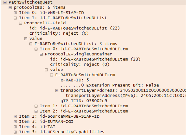
- The target eNodeB creates the S1 eNB GTP TEID and sends the MME the Path Switch Request to inform that the UE has changed the cell.
-
- ECGI (E-UTRAN Cell Global Identifier) is a globally unique cell identifier to which the UE is camping on
- TAI (Tracking Area Identity) is a globally unique tracking area identifier
- E-RAB to be switched indicates the list of EPS bearers to be switched
- S1 eNB GTP TEID indicates the end point of the GTP Tunnel that will be used by the S-GW to identify the target eNodeB
-
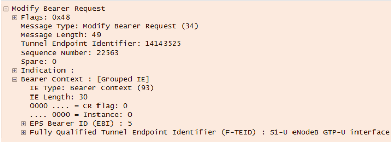
- Upon receiving the Path Switch Request, the MME requests the S-GW to modify EPS bearers by sending Modify Bearer Request per PDN connection. The Modify Bearer Request contains the list of EPS bearers to be modified. The P-GW may need to inform the PCRF about UE’s location has been updated based on the request from the PCRF, when the Gx session was established.
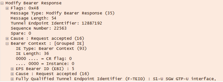
- The S-GW establishes the downlink S1 bearer with the target eNodeB and responds with the Modify Bearer Response, which includes the list of successfully modified EPS bearers.

- The S-GW acknowledges the target eNodeB by sending Path Switch Acknowledge
- The target eNodeB informs the source eNodeB that the handover has been completed successfully by sending UE Context Release.Upon receiving the UE Context Release, the source eNodeB releases all the resources associated with the UE.
References:
- 3GPP TS 36.300 V8.12.0 E-UTRA Overall Descripation
- 3GPP TR 36.881 v 14.0.0 Study on latency reduction techniques for LTE
- 3GPP TS36.331, “Evolved Universal Terrestrial Radio Access Network (E-UTRAN); Radio Resource Control (RRC) Protocol specification”, v12.7.0, Sep 2015
- 3GPP TS25.323, “Packet Data Convergence Protocol (PDCP) specification (release 9)”, v9.0.0, Dec 2012
Related Posts:
- 5G EPS Fallback – 5G to 4G Handover
- 5G SA Inter gNB Handover – N2 or NGAP Handover
- 5G SA Inter gNB Handover – Xn Handover
- 5G SA Handover – Inter gNB-DU and Intra gNB-CU Handover
- 5G NR HO Setup: Handover Testing in Cabled Setup
- LTE Handover Latency Calculation (Access Node)